The Norton Operational Amplifier, LM3900
Source:
http://mysite.du.edu/~etuttle/electron/elect21.htm
The Norton Operational Amplifier, LM3900
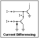 The LM3900 is a 14-pin DIP containing four identical op-amps, each with inverting and noninverting inputs and an output. However, these op-amps are very different from the usual op-amp, and must be used in a completely different way. The usual op-amp responds to a differential voltage at its inputs, but the LM3900 responds to a differential current. Instead of a differential amplifier, the input stage is the current-differencing circuit shown at the right. The current mirror at the noninverting input subtracts the current at that input, I+, from the current at the inverting input, I-, to form the difference current I- - I+ that is furnished to the amplifier with overall gain of 70 dB. If I- is greater than I+, the output saturates low, and if I- is less, the output saturates high. Feedback from the output to the inverting input acts to reduce the difference current, which in normal operation is very small. This is just like the usual op-amp, except with current instead of voltage. The output, however, is a voltage as with the usual op-amp. The label "Norton" refers to the Norton equivalent circuit for a current source.
 Another difference that is immediately obvious is that the inputs are one diode drop, about 0.55 V in the LM3900, above ground, and vary little from that voltage. There is no common-mode voltage range at all! It has been replaced by a common-mode current range by the current differencing. Equal currents supplied to the two inputs are not amplified. The LM3900 is specially useful when only a single power supply is available. Its output swings from very near ground to a diode drop below the positive supply. In these experiments, we'll use a +12 V supply. The LM3900 can use from 4 to 36 V total supply voltage. There is one set of power connections for the four amplifiers, but they are otherwise independent. Connections for the LM3900 are shown at the left.
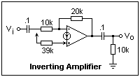 The first circuit to look at is the inverting amplifier, shown at the right. Note the symbol for the Norton op-amp, that has a current source between the inputs, and an arrow on the noninverting input. This is an AC amplifier, with coupling capacitors at input and output so there is no worry about DC bias levels, which can be chosen as necessary. The input and feedback resistors are as with the familiar circuit, and the gain in this case should be -2. The difference is the 39k resistor at the noninverting input. It supplies a current (12 - 0.55)/39 mA to this input, and the output endeavors to supply an equal current to the inverting input, which requires a DC output voltage of (20/39)(12 - 0.55) + 0.55 = 6.4 V, a convenient bias. The bias is set by the current I+, not by a voltage divider, as it would be with the usual op-amp. The LM3900 is very convenient for AC amplifiers. When you test this circuit, the scope traces for input and output can be superimposed with proper setting of the gain, and the inversion is obvious.
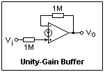 A unity-gain buffer is shown at the left. It looks like the same circuit for the usual op-amp, but here the resistors are necessary. The input resistor turns the applied voltage into a current, while the feedback resistor causes the output to rise to a value supplying an equal current to the inverting input. The circuit is not as precise as the usual one, with small shifts due to the diode drops at the input, but the circuit is useful and furnishes a reasonable input resistance of 1M. The extremely high input resistance of the voltage or FET-input op-amp is not obtained, however.
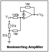 The unity-gain buffer is a special case of the noninverting amplifier, shown at the right with biasing by means of a voltage divider. The divider supplies a current into what is effectively a unity-gain buffer to reproduce its voltage at the output. This amplifier has a gain of +10, of course, or 20 dB. Again, the high input impedance of the voltage op-amp is not obtained.
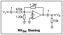 Another biasing scheme for the inverting amplifier is shown at the left. It relies on the diode drop at the inverting input to supply a current proportional to Vbe, which is then amplified by the feedback resistor. In this case, the bias is about 10 x 0.55 = 5.5V. Actual measurement gave 5.7 V. Here, the current supplied by the output is returned to the inverting input, where it flows out the 120k bias resistor, so the bias is positive. In this case, the bias does not depend on the supply voltage.
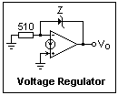 A voltage regulator with a Zener in the feedback loop is shown at the right. The 510Ω resistor supplies a bias current of 0.55/0.51 = 1 mA to the Zener to reduce noise and improve stability. This voltage is added to the Zener voltage at the output. A 4.2 V Zener (1N5230) gave 4.76 V, a 2.3 V Zener (1N5226) gave 2.84 V. A pass transistor can be added at the output for additional current capacity (the LM3900 can be depended on only for about 20 mA when sinking current).
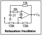 A relaxation oscillator is shown at the left. With the values shown, this circuit oscillated at 3840 Hz, the output swinging from near zero to 11.3 V. The slew rate of the LM3900 was evident in the output waveform. To understand this circuit, assume for simplicity that the output swings from 0 to the supply voltage V. When the output is 0, a current I+ = V/10 μA is supplied to the noninverting input. When the output is V, a larger current I+ = V/5 is supplied. These are the trip levels expressed in currents. When the capacitor is discharged, I- = 0, so the output is high, and the trip level is 3(V/5) = 0.6V. The capacitor charges until its voltage reaches this level, but then the ouput goes low and it begins to discharge again. The lower trip level is 3(V/10) = 0.3V. When the capacitor voltage reaches this level, the ouput again goes high, and the cycle repeats. For a 12V supply, these levels are about 7.2 and 3.6 volts. This is a very rough calculation, so we expect only general agreement. The measured values (from the scope) were 3.0 V and 8.4 V, and the capacitor voltage waveform was quite rounded on top and bottom--in fact, it would be a passable sine wave if you were not too particular. Buffered, this would be an easy way to get a sine wave.
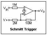 The relaxation oscillator makes use of a Schmitt trigger, with positive feedback. An inverting Schmitt trigger is shown at the right. The input and supply voltages can be exchanged to give a noninverting circuit. The output goes from high to low when the input reaches 7 V, and from low to high when it goes below 6 V, with a hysteresis of 1 V. The hysteresis can be displayed directly on the scope, using the X-Y display. Connect Ch 1 to the input voltage, and Ch 2 to the output. A 100 Hz triangle wave from a function generator makes a suitable input. Alternatively, use 0.5 Hz and watch the dot move. This is a very graphic illustration of Schmitt trigger operation.
The Norton op-amp can also be used to make active filters and oscillators; see the National Semiconductors application note AN-72 for details.
References
The National Semiconductors application note AN-72 of Sept. 1972, revised June 1986, is a good introduction to the LM3900, with a great variety of applications.
Return to Electronics Index
Composed by J. B. Calvert
Created 10 August 2001
Last revised 19 September 2008
Created 10 August 2001
Last revised 19 September 2008


_%E7%94%A2%E5%93%81%E5%90%8D%E7%A8%B1_%E6%99%BA%E6%85%A7%E9%A2%A8%E8%8F%AF%E8%86%A0%E5%9B%8A(Amino%20Essence%20Capsule)_%E5%8C%85%E8%A3%9D%E7%9A%84%E8%A6%8F%E6%A0%BC_60%E7%B2%92,%E5%A1%91%E8%86%A0%E7%93%B6%E8%A3%9D_%E5%8D%B0%E5%9C%A8%E7%99%BD%E8%89%B2%E5%A1%91%E8%86%A0%E9%8E%96%E5%8D%A1%E7%93%B6%E7%9A%84%E6%A8%99%E7%B1%A4%E4%B8%8A%E9%9D%A2%E7%9A%84%E6%96%87%E5%AD%97%E5%85%A7%E5%AE%B9_2016-0821_V001R15_Final%20version_IR93_%E9%97%9C%E9%8D%B5%E5%AD%97%7B%E7%99%BE%E6%AD%90%E4%BB%95%E7%A7%91%E7%A0%94,%20Bio-X%20Lab%7D_designed%20by%20Douglas%20Tang,%20USA_%20(2).png)


沒有留言:
張貼留言